Climate Science Glossary

Term Lookup

Enter a term in the search box to find its definition.

Settings

Use the controls in the far right panel to increase or decrease the number of terms automatically displayed (or to completely turn that feature off).

Term Lookup

Settings


All IPCC definitions taken from Climate Change 2007: The Physical Science Basis. Working Group I Contribution to the Fourth Assessment Report of the Intergovernmental Panel on Climate Change, Annex I, Glossary, pp. 941-954. Cambridge University Press.

Home Arguments Software Resources Comments The Consensus Project Translations About Support

Twitter Facebook YouTube Mastodon MeWe

RSS Posts RSS Comments Email Subscribe


Climate's changed before
It's the sun
It's not bad
There is no consensus
It's cooling
Models are unreliable
Temp record is unreliable
Animals and plants can adapt
It hasn't warmed since 1998
Antarctica is gaining ice
View All Arguments...


Username
Password
New? Register here
Forgot your password?

Latest Posts

Archives

Sun & climate: moving in opposite directions

What the science says...

Select a level... Basic Intermediate Advanced

The sun's energy has decreased since the 1980s but the Earth keeps warming faster than before.

Climate Myth...

It's the sun

"Over the past few hundred years, there has been a steady increase in the numbers of sunspots, at the time when the Earth has been getting warmer. The data suggests solar activity is influencing the global climate causing the world to get warmer." (BBC)

At a glance

Thankfully for us, our Sun is a very average kind of star. That means it behaves stably over billions of years, steadily consuming its hydrogen fuel in the nuclear reaction that produces sunshine.

Solar stability, along with the Greenhouse Effect, combine to give our planet a habitable range of surface temperatures. In contrast, less stable stars can vary a lot in their radiation output. That lack of stability can prevent life, as we know it, from evolving on any planets that might orbit such stars.

That the Sun is a stable type of star is clearly demonstrated by the amount of Solar energy reaching Earth's average orbital position: it varies very little at all. This quantity, called the Total Solar Irradiance, has been measured for around forty years with high accuracy by sensitive instruments aboard satellites. Its average value is 1,362 watts per square metre. Irradiance fluctuates by about a watt either way, depending on where we are within the 11-year long sunspot cycle. That's a variation of no more than 0.15%.

From the early 1970s until today, the Solar radiation reaching the top of Earth's atmosphere has in fact shown a very slight decline. Through that same period, global temperatures have continued to increase. The two data records, incoming Solar energy and global temperature, have diverged. That means they have gone in opposite directions. If incoming Solar energy has decreased while the Earth continues to warm up, the Sun cannot be the control-knob of that warming.

Attempts to blame the sun for the rise in global temperatures have had to involve taking the data but selecting only the time periods that support such an argument. The remaining parts of the information - showing that divergence - have had to be ditched. Proper science study requires that all the available data be considered, not just a part of it. This particular sin is known as “cherry-picking”.

Please use this form to provide feedback about this new "At a glance" section, which was updated on May 27, 2023 to improve its readability. Read a more technical version below or dig deeper via the tabs above!


Further details

Our Sun is an average-sized main sequence star that is steadily using its hydrogen fuel, situated some 150 million kilometres away from Earth. That distance was first determined (with a small error) by a time consuming and complex set of measurements in the late 1700s. It led to the first systemic considerations of Earth's climate by Joseph Fourier in the 1820s. Fourier's number-crunching led him to realise a planet of Earth's size situated that far from the Sun ought to be significantly colder than it was. He was thereby laying the foundation stone for the line of enquiry that led after a few decades to the discovery of what we now call the Greenhouse Effect – and the way that effect changes in intensity as a response to rising or falling levels of the various greenhouse gases.

TSI Solar cycles

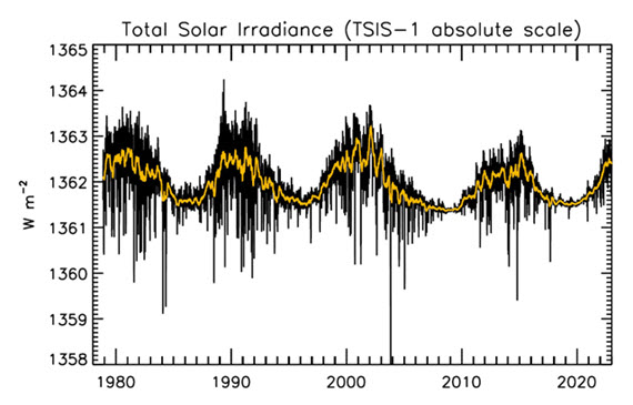
Figure 1: Plot of the observational record (1979-2022) on the scale of the TSIS-1 instrument currently flying on the space station. In this plot, the different records are all cross calibrated to the TSIS-1 absolute scale (e.g., the TSIS1-absolute scale is 0.858 W/m^2 higher than the SORCE absolute scale) so the variability of TSI in this plot is considered to be its “true variability” (within cross calibration uncertainties). Image: Judith Lean.

The Sun has a strong magnetic field, but one that is constantly on the move, to the extent that around every 11 years or so, Solar polarity flips: north becomes south, until another 11 years has passed when it flips back again. These Solar Cycles affect what happens at the surface of the Sun, such as the sunspots caused by those magnetic fields. Each cycle starts at Solar Minimum with very few or no sunspots, then rises mid-cycle towards Solar Maximum, where sunspots are numerous, before falling back towards the end. The total radiation emitted by the Sun – total solar irradiance (TSI) is the technical term – essentially defined as the solar flux at the Earth's orbital radius, fluctuates through this 11-year cycle by up to 0.15% between maximum and minimum.

Such short term and small fluctuations in TSI do not have a strong long term influence on Earth's climate: they are not large enough and as it's a cycle, they essentially cancel one another out. Over the longer term, more sustained changes in TSI over centuries are more important. This is why such information is included, along with other natural and human-driven influences, when running climate models, to ask them, “what if?"

An examination of the past 1150 years found temperatures to have closely matched solar activity for much of that time (Usoskin et al. 2005). But also for much of that time, greenhouse gas concentrations hardly varied at all. This led the study to conclude, "...so that at least this most recent warming episode must have another source."

TSI vs. T
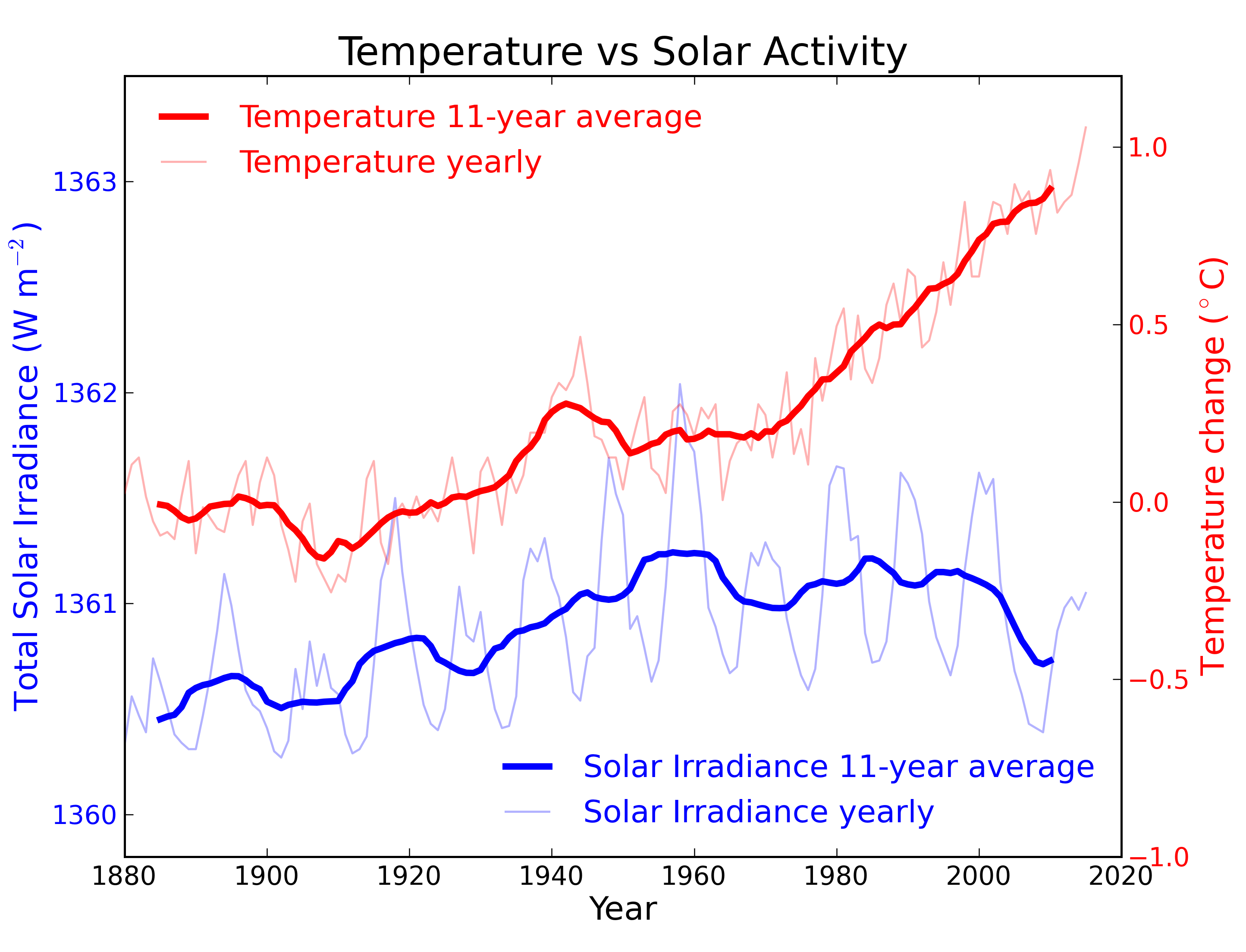
Figure 2: Annual global temperature change (thin light red) with 11 year moving average of temperature (thick dark red). Temperature from NASA GISS. Annual Total Solar Irradiance (thin light blue) with 11 year moving average of TSI (thick dark blue). TSI from 1880 to 1978 from Krivova et al. 2007. TSI from 1979 to 2015 from the World Radiation Center (see their PMOD index page for data updates). Plots of the most recent solar irradiance can be found at the Laboratory for Atmospheric and Space Physics LISIRD site.

The slight decline in Solar activity after 1975 was picked up through a number of independent measurements, so is definitely real. Over the last 45 years of global warming, Solar activity and global temperature have therefore been steadily diverging. In fact, an analysis of solar trends concluded that the sun has actually contributed a slight cooling influence into the mix that has driven global temperature through recent decades (Lockwood, 2008), but the massive increase in carbon-based greenhouse gases is the main forcing agent at present.

Other studies tend to agree. Foster & Rahmstorf (2011) used multiple linear regression to quantify and remove the effects of the El Niño Southern Oscillation (ENSO) and solar and volcanic activity from the surface and lower troposphere temperature data.  They found that from 1979 to 2010, solar activity had a very slight cooling effect of between -0.014 and -0.023°C per decade, depending on the data set. A more recent graphic, from the IPCC AR6, shows these trends to have continued.

AR6 WGI SPM Figure 1 Panel p

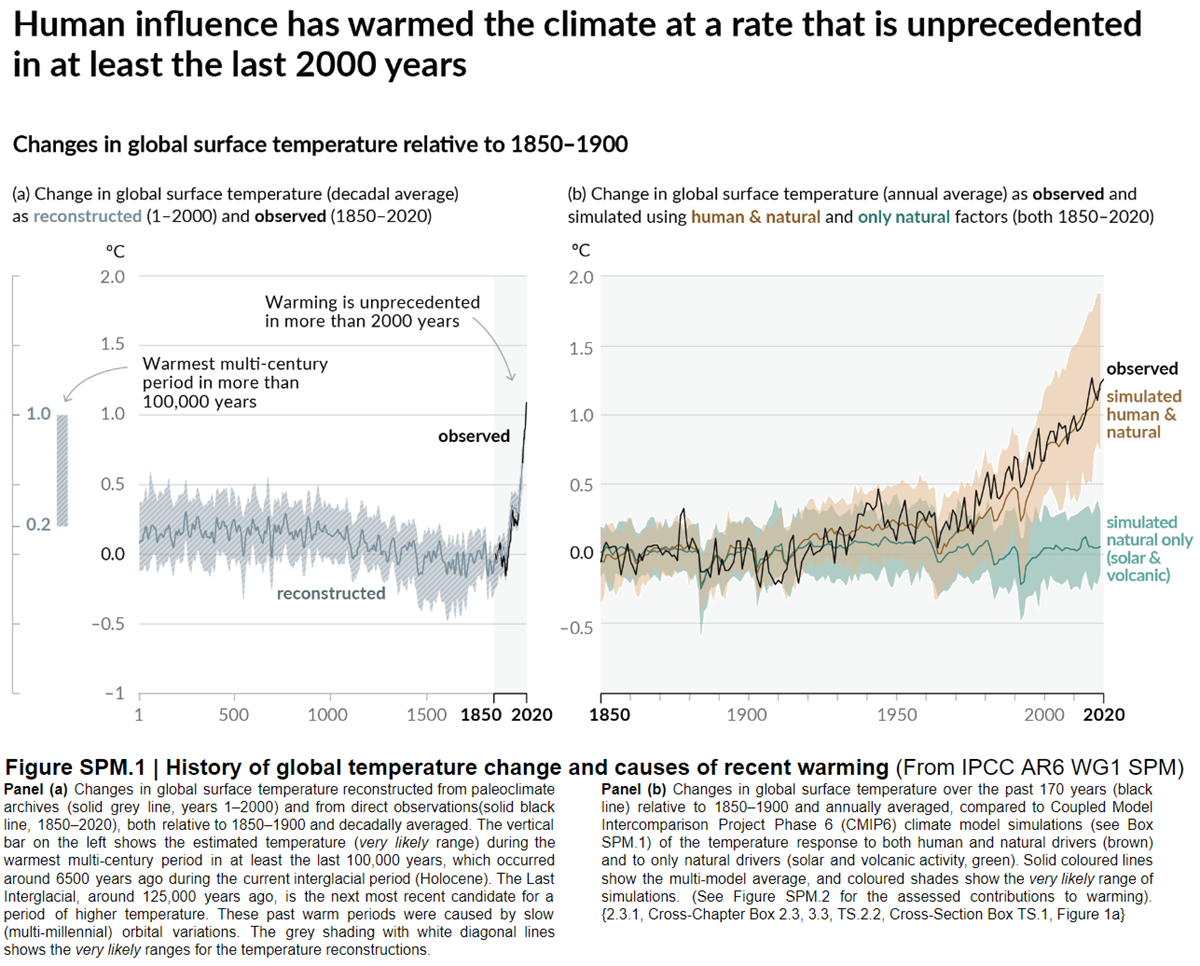
Figure 3: Figure SPM.1 (IPCC AR6 WGI SPM) - History of global temperature change and causes of recent warming panel (b). Changes in global surface temperature over the past 170 years (black line) relative to 1850–1900 and annually averaged, compared to Coupled Model Intercomparison Project Phase 6 (CMIP6) climate model simulations (see Box SPM.1) of the temperature response to both human and natural drivers (brown) and to only natural drivers (solar and volcanic activity, green). For the full image and caption please click here or on the image.

Like Foster & Rahmstorf, Lean & Rind (2008) performed a multiple linear regression on the temperature data, and found that while solar activity can account for about 11% of the global warming from 1889 to 2006, it can only account for 1.6% of the warming from 1955 to 2005, and had a slight cooling effect (-0.004°C per decade) from 1979 to 2005.

Finally, physics does not support the claim that changes in TSI drive current climate change. If that claim had any credence, we would not expect to see the current situation, in which Earth's lower atmosphere is warming strongly whereas the upper atmosphere is cooling. That is exactly the pattern predicted by physics, in our situation where we have overloaded Earth's atmosphere with greenhouse gases. If warming was solely down to the Sun, we would expect the opposite pattern. In fact, the only way to propagate this myth nowadays involves cherry-picking everything prior to 1975 and completely disregarding all the more recent data. That's simply not science.

Longer-term variations in TSI received by Earth

It's also important to mention variations in TSI driven not by Solar energy output but by variations in Earth's orbit, that are of course independent of Solar activity. Such variations, however, take place over very long periods, described by the Milankovitch orbital cycles operating over tens of thousands of years. Those cycles determine the distance between Earth and the Sun at perihelion and aphelion and in addition the tilt the planet's axis of rotation: both affect how much heat-radiation the planet receives at the top of its atmosphere through time. But such fluctuations are nothing like the rapid changes we see in the weather, such as the difference between a sunny day and a cloudy one. The long time-factor ensures that.

Another even more obscure approach used to claim, "it's the sun" was (and probably still is in some quarters) to talk about, "indirect effects". To wit, when studies can't find a sufficiently large direct effect, bring even lesser factors to the fore, such as cosmic rays. Fail.

In conclusion, the recent, post 1975 steep rise in global temperatures are not reflected in TSI changes that have in fact exerted a slight cooling influence. Milankovitch cycles that operate over vastly bigger time-scales simply don't work quickly enough to change climate drastically over a few decades. Instead, the enormous rise in greenhouse gas concentrations over the same period is the primary forcing-agent. The physics predicted what is now being observed.

Last updated on 27 May 2023 by John Mason. View Archives

Printable Version  |  Offline PDF Version  |  Link to this page

Argument Feedback

Please use this form to let us know about suggested updates to this rebuttal.

Related Arguments

Further viewing

Related video from Peter Sinclair's "Climate Denial Crock of the Week" series:

Further viewing

This video created by Andy Redwood in May 2020 is an interesting and creative interpretation of this rebuttal:

Myth Deconstruction

Related resource: Myth Deconstruction as animated GIF

MD Sun

Please check the related blog post for background information about this graphics resource.

Denial101x videos

Related lecture-videos from Denial101x - Making Sense of Climate Science Denial

and

Additional video from the MOOC

Expert interview with Mike Lockwood

Comments

Prev  10  11  12  13  14  15  16  17  18  19  20  21  22  23  24  25  26  27  28  29  Next

Comments 476 to 500 out of 1040:

  1. Near the surface, most is re-radiated by GHGs as required for the surface to radiate as it does. Only 37 W/m2 needs to get far from the surface as required to produce heat balance using the other K&T values.
  2. The other K&T updated values referred to are the 78 of incoming absorbed by the atmosphere, the 17 thermals and 80 latent. The 78 seems high. Reduction of this increases thermalization by the same amount and decreases back radiation by the same amount. Reducing the 78 to 10 increases thermalization by 68 to 105 and reduces back radiation from the atmosphere to 237. That which gets from average clouds to ground remains at 13.
  3. "Near the surface, most is re-radiated by GHGs as required for the surface" This can be a point of confusion: people throw around terms like 're-radiate' a bit too loosely. The rate of thermalization is sufficiently high in the great majority of the atmopshere by mass and by optical thickness that GHGs do not radiate by fluorescence - which is what some people seem to think (and they may get that idea from the term 're-radiate'); instead, GHGs and other greenhouse agents emit photons mainly from thermal energy, which they can get from the bulk air from molecular collisions.
  4. In some cases, it may be necessary to consider I not just along specific directions and at specific wavelengths, but also by polarization. At a given direction q and wavelength L, the intensity I(q,L) is the sum of contributions of I from each polarization P: I(q,L,P). Scattering and emission/absorption cross sections could be functions of polarizations in cases where the particles involved lack spherical symmetry and are not oriented at random. Within the atmosphere, ice crystals can have prefered orientations, and rain drops flatten slightly as they fall (though I wouldn't think the later has much significance overall). Reflection where there is a relatively sharp change in the index of refraction is also a function of polarization. ------- Contributions to the intensity I(q,L,P) could also be seperated by phase - I don't know if there would be much point in this except in finding the brightness temperature of laser light that corresponds with the entropy; perfect blackbody radiation, as well as being isotropic across all q, is evenly distributed over polarizations P and phases (it is incoherent); so it would be of interest to know the temperature of a blackbody that can emit radiation with I(q,L,P) for a single phase equal to the intensity I(q,L,P) of some coherent radiation (defining brightness temperature with such specificity, any significant nonzero I that is either perfectly monochromatic (dL = 0), perfectly polarized (dP = 0), or perfectly coherent would have infinite brightness temperature and zero entropy - it would be all work and no heat). --------- Particles much smaller than a wavelength of radiation can change the overall index of refraction, but an even distribution of such particles would not cause a spatial variation in the index of refraction. When the index of refraction for the bulk medium (as opposed to just the scattering and absorption/emission agents) must be considered, then it will be more convenient to use frequency v instead of wavelength L to specify the part of spectrum considered. The monochromatic intensity is better given as the intensity per frequency interval dv because wavelength intervals dL can change. Alternatively, one could refer to L# as the wavelength the radiation of that frequency would have if in a vacuum (and then define the spectral intensity as the intensity per unit L#. Following I along a path when the real component of the index of refraction, n, changes, I in the absence of scattering, reflection, or absorption and emission, is not what is conserved along the path; it is I * n^2 that is conserved. This is because a unit of solid angle dw that envelopes a group of rays will be compressed or expanded by the square of the ratio of different n values following the refracted paths. This relates to total internal reflection: for a flat surface, there is a cone of accepantance through which some radiation can pass from high n to low n (100 % if there is a perfect antireflection coating (if and when such a thing exists); outside of that cone, there will be (in the absence of scattering and absorption) 100 % reflection. If the transition from high n to low n is gradual, the cone of acceptance applies, but instead of reflecting at a specific interface, ray paths outside the cone curve back gradually, as ray paths within the cone curve to spread out to fill the full hemisphere of solid angles (additional transition to lower n defines a narrower cone of accetance for the rays that reach over the larger variation of n without curving back or reflecting). Relative to wavelength, small-scale texterization can mimic a gradual variation of n and reduce reflection within the cone of acceptance in that way; larger-scale texterization can reduce reflection via successive intersections of a ray with the interface, so that the amount that transmits across the interface accumulates with each intersection; in that case, the cone of acceptance may not be so easily defined due to different angles, but ...
  5. I'm OK with radiated. I don't know which is less confusing to most people.
  6. (continued)... ... but for the flux per unit area (integrated over solid angle), the fraction that is trapped by total internal reflection remains the same. ------------- CORRECTION: following ray paths without scattering, absorption and emission, or reflection, over variations in n: it is I / n^2 that is conserved. Not I * n^2 . ------------- Considering the case where there is no reflection, scattering, or emission and absorption along a path over varying n, the conservation of I / n^2 implies that blackbody radiation Ibb(v,T) must be proportional to n^2, so that observed blackbody radiation at any given n, such as n=1 (vaccuum, approximately in air), has the same intensity regardless of the n at the location of emission. When following ray paths, the direction of the path obviously can bend as n varies, so the direction Q is a function of location (with location itself being a function of direction from another given location - outside of some simplified conditions, calculating location and direction requires integration of directional changes along the path from an initial location.) Q in general has two components, which can be the angles in spherical coordinates; the q used earlier is the angle from the top pole (the colatitude: latitude - 90 deg), which is all that is necessary if conditions do not vary in planes perpendicular to the axis of the coordinate system; more generally, the angle around the axis (analogous to longitude) could also be specified. n can depend on direction in materials, in which case n is a function of Q. I would guess it could also be a function of polarization P (is that what produces the double images through calcite?: note to self - look up birefringence). Many people are aware that in materials it is often a function of frequency v (why we have rainbows). Of course, n = c_vacuum / c_material, the ratio of the phase speed in a vacuum to the phase speed in the material (in the direction being considered) ... BUT when n is a function of frequency v, the group velocity - the direction and speed at which energy is carried by wave amplitude propagation - can be different from the phase direction and speed. Presumably, they will still be in the same direction (or directly opposite each other, as in the case of certain metamaterials with a negative index of refraction) when n does not vary with direction; I wonder what happens if n varies in direction; then perhaps group velocity might be at some angle to phase propagation - in which case, the ray path to follow when evaluating changes in I would be along the path defined by group velocity, ... and the n for which I / n^2 is conserved in the absence of reflection, scattering, and absorption and emission, is (??????). (PS it is actually common to deal with fluid mechanical waves in the atmosphere (and, I presume, the ocean) (gravity waves, inertio-gravity waves, Rossby waves, Rossby-gravity waves, Kelvin waves) for which the group velocity and phase propagation, relative to the air (as it moves or doesn't), are perpendicular to each other.) PS n is the real component of the index of refraction; the index of refraction can actually be a complex value, with an imaginary component that is related to the absorption cross section per unit volume (the absorption coefficient). ------------ Fortunately, radiation transfer through the atmosphere is little affected by variations in the real component of the index of refraction of the bulk air (obviously it figures into the scattering properties of cloud droplets and aerosols). The most significant effects I am aware of is the twinkling of starlight and the shifting of the sunset and sunrise times. (Also, gravitational redshifting is not a big effect for radiation into and out of the Earth; I won't bother going into the relativistic effects on radiation here.) But it is interesting to consider what qualitative effect it would have, as well as the spherical geometry of the Earth (the layers of the atmosphere have slightly greater area than the surface, and so can emit the same total power at a slightly lower temperature than otherwise.) The effect of n slightly greater than 1 increases the length of the day as seen from the surface. This implies that, aside from atmospheric albedo contributions, the surface of the Earth intercepts a greater amount of sunlight than would actually pass through it's cross sectional area. Indeed, the implication of the index of refraction of the atmosphere being slightly greater than space is that the Earth would appear slightly bigger from space than it actually is - In general, any given spherical surface below the 'top' of the atmosphere will be magnified by the n greater than 1 of the air above it - but obviously, cannot appear any bigger than the spherical boundary of the layers of air that are magnifying it. This happens because, when looking at the edge of the Earth, the line of sight intersects surfaces of constant n within the atmosphere around the Earth at a glancing angle and is bent toward the Earth's surface; the visible edge of the Earth corresponds with the lines of sight that bend only enough to reach the surface nearly horizontally, and those lines of sight will reach the surface somewhat behind the front half of the Earth (as defined by viewing position). (This description applies to the view from an infinite distance; obviously, without refraction, much less than half the Earth would be visible from nearby, but refraction would extend the area visible by some amount.) If n were higher for solar radiation than terrestrial radiation, then it would increase the solar heating of the Earth and any given layer of atmosphere more than it would increase the LW radiative cooling to space from the same vertical levels. I don't know if that is the case, but it is a very small effect that can be ignored for most purposes anyway. Most of the radiation to space comes from within the troposphere, and a majority of direct solar heating occurs at the surface (or within the surface material, as in the ocean). For a very quick analysis to put some likely bound on the effect of this, suppose the radiation to space came entirely from a height of 16 km above the surface (that's within the stratosphere outside of the tropics, and close to the tropopause within the tropics), while all solar heating were at the surface. In that case, the effective surface area emitting to space would be about 2*(16/6371) ~= 0.5 % larger than the surface that is heated by the sun, which would allow the effective emitting temperature to be (0.5 % /4) = 0.125 % smaller than that required to radiate to space enough to balance solar heating with the same area as the surface. That would be about 2.55 / 8 ~= 0.32 K cooler. Not very much compared to a 33 K greenhouse effect overall. So both the increase in area with height and the refraction by the air can be ignored for climatologically-relavent radiative fluxes. Also note that the refraction would tend to counteract the effect of greater area with height, since it would magnify areas beneath greater amounts of atmosphere more than higher level areas. ------------
  7. ________________________ MORE ABOUT REFRACTION: COMPLEX N: Let the complex index of refraction be N. Previously I used n to represent the real component of the index of refraction. It would be better to refer to that as nr. (From class notes): Imaginary component of the index of refraction ni: The absorption coefficient (equal to the absorption cross section per unit volume) = 4 * pi * ni / L# where L# is the wavelength in a vacuum of radiation with the same frequency v. ---- The real and imaginary components of the index of refraction, N = nr + i*ni , do not vary independently of each other over v or L#. nr and ni are related by the Kramer-Kronig relationships. ---- My understanding is that, When (magnetic) permeability is not different from a vacuum, the complex dielectric coefficient is equal to the square of the complex index of refraction. ------------------------ **** IMPORTANT CLARIFICATION/CORRECTION **** The statement that I / nr^2 was conserved in the absence of absorption, reflection, or scattering is true at least in so far as the group velocity and phase propagation are in the same direction. However, my intent was that the change in I over a distance dx along a ray path would then be given by letting I# = I / nr^2, and then the differential formula would be: d(I#(Q,v,P)) = Ibb#(v,T) * ecsv - I#(Q,v,P) * (acsv + scsv) * dx + Iscat * dx where Ibb#(v,T) = Ibb(v,T) * nr^2 is the blackbody intensity for the index of refraction (given per unit frequency dv and per unit polarization dP) and: ecsv, acsv, and scsv are the emission, absorption, and scattering cross sections per unit volume, Iscat * dx is the radiation scattered into the path from other directions, and any reflection (removing and/or adding to I along the path) at an interface within dx is included in the scattering terms. And of course, ecsv = acsv if in local thermodynamic equilibrium. --- Such a relationship is constructed with I# = I/ nr^2 is based on Snell's law where nr*sin(q) = constant (not quite true, actually (???) - see below) is the relationship that determines q as a function of N, where N varies only in one direction z (planes of constant N are normal to the z direction) and q is the angle from the z direction. I# = I / nr^2 is derived from Snell's law, by determining that the solid angle dw that encompasses a group of rays expands or compresses with variation in the index of refraction, specifically so that dw is proportional to 1/nr^2. **** HOWEVER: When N is complex, Snell's law actually still uses the complex N, not just it's real component. I haven't entirely figured out what that means for q, though I have the impression that nr*sin(q) = constant should be at least approximately true. Snell's law itself is based on the requirement that the phase surfaces of incident and tranmitted waves line up at an interface, and that the phase speed is inversely proportional to N when N = nr. What is the phase speed when N has a nonzero imaginary component? And then there is also the complexity of what happens if group velocity is not in the same (or exact opposite) direction as the wave vector (the wave vector is normal to phase planes and thus is in the direction of phase propagation). -------- So for the time being, let I# = I / n^2, where n is whatever N-related value that works in that relationship and also: d(I#(Q,v,P)) = Ibb#(v,T) * ecsv - I#(Q,v,P) * (acsv + scsv) * dx + Iscat * dx At least when N = nr and N is not a function of direction Q, n = N = nr. ________________________ REFLECTION AND EVANESCENT WAVES: When the entirety of wave amplitude and wave energy is reflected by an interface (as in total internal reflection), some of the energy actually penetrates across the interface. The portion of the wave across the interface that is associated with the reflected portion of the wave is called an evanescent wave. The energy and amplitude of the evanescent wave decay exponentially away from the interface into the region where the reflected wave cannot propagate (in the time average, there is no group velocity component normal to the interface within the region of the evanescent wave). The evanescent wave is mathematically required for continuity of the electric and magnetic fields, and for the time-integrated divergence of the energy flux to be zero over a wave cycle when there is a constant incident energy flux (and no absorption or emission). If there is another interface, beyond which the wave could propagate, then waves energy can emanate from that interface to the extent that the evanescent wave penetrates to it. This flux of energy must pull energy from the evanescent wave, which results in reduced reflection from the first interface. This is how wave energy can 'leak' through a barrier. The same general concept applies to mechanical waves, including fluid mechanical waves in the atmosphere and ocean, and to quantum mechanical waves - electrons tunnel through barriers via evanescent waves. Absorption within the region of the evanescent wave allows some net energy flow across the interface and thus reduces the reflectivity, so that even when a nonzero 'transmissivity' is not allowed except for tunneling, the reflectivity can be less than 1. I'm not sure but I think absorption on the side of a transmitted wave might also reduce reflectivity even when trasmission is allowed. (??) ________________________ I think I actually have the equations necessary to find some answers to questions just raised (if unable to find them elsewhere), but it will take time and it isn't pertinent to the matter here (I've already gone off on these tangents far enough). ________________________ GROUP VELOCITY: Group Velocity in geometric space specifically is equal to the gradient of the angular frequency (omega = 2*pi*v) in the corresponding wave vector space (a wave vector is a vector with components of wave numer; wave number is equal to 2*pi / wavelength measured in the correpsonding dimension; the wavelength in the direction of phase propagation is equal to 2*pi divided by the magnitude of the wave vector). Where the wavevector = [k,l,m], where k,l,and m are the wave numbers in the x, y, and z directions Angular frequency = omega group velocity in x,y,z space = [ d(omega)/dk , d(omega)/dl , d(omega)/dm ] phase speeds cx, cy, cz in directions x,y,z cx = omega/k cy = omega/l cz = omega/m IN the direction of phase propagation, the phase speed c and wavelength L are related as: c = v*L -------- IT IS POSSIBLE for some materials, at some values of v, to have a real component of the index of refraction less than 1. This (tends to or approximately??) corresponds to a phase speed that is greater than the speed of light in a vaccuum. This does not violate special relativity; the group velocity is the direction and speed of energy flux and information transport, and the group velocity will not be larger than the speed of light in a vaccuum. ________________________ Relativity: Effects are gravitational lensing and gravitational redshift, and effects related to relevant motion (of the Earth and sun, for example. One effect of relative motion is that small dust particles orbiting the sun tend to fall in toward the sun over time (their semimajor axes shrink) because as they orbit, they recieve radiation more from their leading side because of their motion, so radiation pressure tends to slow them down. Of course, radiation pressure also pushes them out - on the other hand, any stable orbit would be such that the outward radiation pressure would only partly cancel the gravitational acceleration, thus causing a slower but stable orbit in the absence of the radiative pressure torque on the orbit from orbital velocity. Larger objects of a given density have more mass per unit surface area and are less affected by radiation pressure. ________________________ Another way of looking at magnification by atmospheric refraction (considering mainly N = nr cases): For flat surfaces, leaving some vertical level moves upward across falling n values, total internal reflection keeps a portion of rays trapped; the other rays spread out to fill the full hemisphere solid angle, reducing the intensity and, if the radiation was initially isotropic, keeping the total upward flux per unit horizontal area proportional to n^2 at each level (so long as n only either decreases or remains constant with height). But for concentric spherical surfaces (with N decreasing outward to N = 1), the cone of acceptance defined for flat interfaces is narrower than the cone of rays that is able to escape upward to any given level, because as the rays curve over and downward, the interfaces - the locally defined horizontal surfaces - curve downward. Thus, the height to which any ray can reach is raised, and a greater solid angle of rays escapes all the way out to N = 1. This means a greater total upward flux per unit horizontal area reaches to any given height and to N = 1. But the intensity of the radiation still falls by the same amount as it passes to lower N (being proportional to N^2); so the greater flux requires a greater solid angle - hence, the underlying surfaces that are the source of the fluxes occupy a greater solid angle from any given viewing point - they appear larger - hence they are magnified. Some rays will still be trapped, so the magnification must be less than N^2. ---------- From some class notes: N of the air, in the visible part of the spectrum, at STP (standard temperature and pressure) is about 1.0003. Near sea level conditions are broadly similar to STP. If N ~= 1.0003, then N^2 ~= 1.0006. In that case, the effect on I would be a 0.06 % increase relative to I in a vaccuum. The magnification of the surface as seen from space cannot be more than that (and is also limited by the vertical extent of different N values). The magnification of higher layers will tend to be less because N will tend to decrease with height toward 1. ------------------ A particular important point about the climatic effects of increasing surface area and changes in N with height is that they would not be a source of significant positive or negative feedback (at least for Earthly conditions). As the greenhouse effect increases, the distribution of radiative cooling to space does shift upward. But a doubling of optical thickness per unit mass path would only shift the distribution within the atmosphere of transmissivity to space upward by about 5 km, give or take ~ 1 km (it is less at heights and locations where the temperature is colder, more where warmer). Doubling CO2 would have that effect only over the wavelengths in which it dominates (covering roughly 30 % of the total radiant power involved), and not quite even that, since at most wavelengths, emission cross sections are smaller with increasing height, at least for the troposphere and maybe lower stratosphere, and also, there would be some overlaps with clouds. Also, the tropopause level forcing would be due mostly to expansion in the wavelength interval in which CO2 significantly blocks radiation from the surface, water vapor, and clouds, given the shape of the CO2 absorption spectrum and that the central part of the CO2 band is saturated at the tropopause level with regards to further radiative forcing. The water vapor feedback is less than a doubling of water vapor, and water vapor density decreases much faster with height than air density within the troposphere. The height of the troposphere will shift upward to lower pressure as the temperature pattern shifts, so the highest cloud tops will be higher, but not by much in terms of affecting the emitting surface area. An upward shift in the LW radiative cooling distribution of about 5 km would result in about a 0.1 K cooling; it seems that a vertical shift less than 5 km likely causes a warming of about 3 +/- 1 K, 20 to 40 times larger (PS the vertical shift includes all LW radiative feedbacks; if there were no positive LW feedbacks, the warming would be reduced, but so would the vertical shift. If SW feedbacks were excluded, then maybe the warming would be at the lower end of the range given, I think). What would truly be required to result in a 0.1 K cooling by this process is if all LW radiative cooling that occured within the troposphere and at the surface were confined to be below 5 km from the tropopause initially (or else, to have the tropopause level rise to accomodate the shift?), and then to have the whole distribution raised 5 km, so that there would then be no LW cooling below 5 km from the surface. This would actually cause warming of roughly 30 K, given a lapse rate of 6 K/km. Thus the cooling by area increasing with height would be roughly just 1/3 % of the warming. There is yet one other way to vertically shift the LW cooling distribution: Thermal expansion. The atmospheric mass in the troposphere would only expand about 1 % in response to a 3 K warming, which would only contribute a 0.002 K cooling for an initial 10 km effective level for LW cooling. (This mass expansion is a seperate issue from the increasing height of the tropopause mentioned in the previous paragraph - the later is a rise in the tropopause relative to the distribution of mass - essentially a transfer of mass from the stratosphere to the troposphere. This is actually an expected result of global warming in general, although nothing on the order of 5 km so far as I know). --------- Feedbacks involving changes in the index of refraction of the air, and forced changes in the index of refraction of the air, can also be expected to be insignificant. ________________________ MORE ON THE 'I CAN SEE YOU AS MUCH AS YOU CAN SEE ME' PRINCIPLE (THAT IS REQUIRED if THE SECOND LAW OF THERMODYNAMICS IS TO APPLY): SPECULAR REFLECTION: For simplicity of illustration, consider an interface between materials, where on side A, N = NA, and on side B, N = NB, and in both cases, let the imaginary component be zero. Let N be invariant over direction within each material. Identify directions Q by two angles: Q = (q,h). q is the angle from the normal (perpendicular) to the interface (specifically, measured from the direction leaving the interface on the side that q is taken), and h is the angle around the normal to the surface; h going from 0 to 360 deg at constant q traces a circle in a plane parallel to the interface; rather than reversing the direction h is measured across the interface to keep the same overall coordinate system (right-handed or left-handed) for each side A and B, measure h on each side in the same sense (clockwise or counterclockwise) as viewed from just one side. Consider four ray paths that approach this interface. Two rays, 1 and 2, are incident from side B with directions Q1 and Q2, respectively. Two other rays, 3 and 4, are incident from side B with directions Q3 and Q4. Q1 = (qA,h0) Q2 = (qA,-h0) Q3 = (qB,-h0) Q4 = (qB,h0) So rays 1 and 2 have the same q = qA, rays 3 and 4 have the same q = qB, and 1 and 4 have the same h = h0, while 2 and 3 have the same h that is the opposite of the h of the other two rays. Let NA*sin(qA) = NB*sin(qB). A portion of each rays is reflected (denoted r) and a portion is transmitted (denoted t). For example, from the incident ray 1, the reflected ray is 1r and the transmitted ray is 1t. Notice: If all incident rays intersect the interface at the same point, then: ray 1t goes backwards along the path of ray 3 ray 3t goes backwards along the path of ray 1 ray 1r goes backwards along the path of ray 2 ray 2r goes backwards along the path of ray 1 ray 2t goes backwards along the path of ray 4 ray 4t goes backwards along the path of ray 2 ray 3r goes backwards along the path of ray 4 ray 4r goes backwards along the path of ray 3 etc. The incident rays have spectral (monochromatic) Intensities I# = I/N^2 of I1, I2, I3, I4. Along paths 1, 2, 3, and 4, the I/N^2 toward the interface are: I1 I2 I3 I4 IF the reflectivity from side A is RA and the reflectivity from side B is RB then: Along paths 1, 2, 3, and 4, the I/N^2 away from the interface are: RA*I2 + (1-RB)*I3 RA*I1 + (1-RB)*I4 RB*I4 + (1-RA)*I1 RB*I3 + (1-RA)*I2 Suppose each ray is emanating from a blackbody, and each blackbody has the same temperature. In that case, the net intensity (forwards - backwards) = 0 along each path so that there is no net heat transfer, assuming the second law of thermodynamics holds for the consequences of reflection and refraction. RA*I2 + (1-RB)*I3 - I1 = 0 RA*I1 + (1-RB)*I4 - I2 = 0 RB*I4 + (1-RA)*I1 - I3 = 0 RB*I3 + (1-RA)*I2 - I4 = 0 Also, I1 = I2 = I3 = I4. Then: RA + (1-RB) = 1 RA + (1-RB) = 1 RB + (1-RA) = 1 RB + (1-RA) = 1 Each relationship yields the same conclusion: RA = RB = R. Reflectivity is the same for any two rays approaching the same interface from opposite sides in which each of their transmitted rays goes backwards along the other incident ray. Reflectivity can vary with polarization P, so this only applies if either the incident rays are completely unpolarized or polarized specifically to fit some variation of N over P (as in perfect blackbody radiation), or if the intensity is evaluated for each polarization seperately. The formulas (one for parallel and one for perpendicular polarizations) for reflectivity (Fresnel relations) as a function of NA/NB and qA or qB (each q determines the other) give the same R for RA and RB for each polarization. The Fresnel relations are not determined by the second law of thermodynamics; they are determined (at least in part) with the constraint that the electric and magnetic fields only vary continuously in space; they each have only one value at any one location and time, including on the interface. I'm not sure if it is necessary for deriving the relations, but the Fresnel relations would also have to fit with the conservation of radiant energy (except for allowed sources and sinks such as emission and absorption). An interesting further point: Along ray 1, the I/N^2 coming back from the interface = R * I2 + (1-R) * I3 What happens to the radiation going toward the interface along I1 ? R * I1 is reflected backward along ray path 2, and (1-R) * I1 is transmitted backward along ray path 3. In other words, the distribution of where the radiation going forward along a path reaches matches the distribution of the sources of the radiation that goes backwards along the same path (before weighting by the strength of each source). ------ There should be a similar pattern of behavior for scattering. That is, if I is isotropic, then the I scattered out of a path must equal the I scattered into the path over the same unit of path dx. Otherwise, anisotropy in I# could spontaneously arise, which would break the second law of thermodynamics (clever use of such spontaneous anisotropy could run a perpetual motion machine). Of course, a scattering cross section per unit volume, scsv, can vary over direction, but it should (except for macroscopic scatterers where absorption cross section on one side can be matched with scattering cross section on the opposite side) be the same for a pair of opposing directions along a ray path. More generally: What I expect is that the distribution over directions of radiant intensity that is scatterd out of a ray going in the x direction over a distance dx should fit the distribution of the source directions of radiant intensity that is scattered into the ray in the same dx to go in the negative x direction, before weighting by anisotropy of the source direction intensities. When the same type of scattering has the same scattering cross section in all directions (and the scattering distribution has 0-fold rotational symmetry about the direction from which I is scattered), I think this can be shown to be true: Consider a fraction of radiation that is scattered by an angle q' into the solid angle dw in the direction Q2, from an initial direction Q1 and solid angle dw. The same angle of scattering applies to radiation that is scattered from the direction Q2 into the direction Q1. Thus the same fraction of radiation is scattered into Q2 from Q1 as is scattered from Q1 into Q2. ________ CONCLUSION (in the expectation that more complex forms of scattering and reflection and dependence on complex N values that vary over direction, and where group velocity is the direction of propagation of intensity, while phase propagation may be in a different direction - that these situations still fit the general concepts illustrated above): At a given frequency v, and if necessary, polarization P (could be a function of position along paths): At a reference point O along a path in the direction Q (which can bend as refraction requires), with distance forward along the path given by x: Considering the forward intensity I#f in the solid angle dw, the distribution of where I#f goes is proportional to the derivative of the transmission with respect to x. It can be visualized by considered a distribution of distance x over dw, where each cross section per unit area normal to the path over the unit distance dx (including reflectivity at any interface within dx) occupies a fraction of dw equal to itself multiplied by the transmission over x. The solid angle dw is the sum of many fractions of dw that are each filled by cross section at a different distance. The fractions are the fractions of I#f that are intercepted at the corresponding distances. They are also the fractions of the total visible cross section from point O at the corresponding distances. This is essentially a distribution of dw over x, that describes the distribution over x of what is visible along x from point O and of how much visibility of I#f at O exists at x. d(dw)/dx can be integrated along x to give a visible cross section per unit area of 1. I#f(O) * d(dw)/dx is the interception at x per unit dx of whatever I#f passes through O. Integration of d(I#b(x)) * d(dw)/dx gives the total backward intensity I#b(O) that reaches O; it sums the proximate sources of I#b(O) over the fractions of dw that correspond to a distribution over x. This can be extended farther. Suppose we are interested in the absorption of I#f. For all the fractions of dw that are scattering or reflection cross sections per unit area, the fate of those fractions of I#f can be traced farther, through successive scatterings and reflections, until every last bit is absorbed. This will be a distribution of dw that may extend outside of the path and over other paths, perhaps over some volume. It is the distribution of the absorption of I#f(O). Assuming local thermodynamic equilibrium within each unit volume, It is also the distribution of the emission of I#b(O) - multiplying the distribution density by I#bb(T) and integrating over the distribution gives the I#b(O) value, where I#bb(T) is the blackbody intensity (normalized relative to refraction) as a function of T, however it varies over space. I#f(O) also has an emission distribution that can be found, tracing back in the opposite direction from point O. The net I# at point O in the forward direction is I#(O) = I#f(O) - I#b(O), and will be in some way proportional to the difference in temperature T (specifically, the difference in the weighted average of Ibb#(T) over the emission distribution) between the emission distribution of I#f(O) and the emission distribution of I#b(O). Assuming the forward direction is from higher to lower temperature within the emission distributions, if the two distributions extend over a larger range in T (at a given overall average T), then the net radiant transfer I#(O) will be larger; if the two distributions extend over a smaller range in T (at a given overall average T), then the net radiant transfer I#(O) will be smaller. I#(O) can be changed by either changing the emission distributions or the temperature distributions. Increasing overlap of the distributions will tend to reduce I#(O) (the distribution of emission for either I#b(O) and/or I#f(O) can wrap around the point O when there is sufficient scattering and/or reflection). EXAMPLES: ----------- PURE EMISSION AND ABSORPTION (loss to space is 'absorption' by space for climatological purposes): The emission distributions of each of I#f(O) and I#b(O) are entirely along the ray path, with zero overlap. Each distribution density decays exponentially from point O in optical thickness coordinates; the distributions are more concentrated near point O in (x,y,z) space when there is greater cross section per unit (x,y,z) volume. If there is an emitting/absorbing surface (approximately infinite optical thickness per unit distance), that the ray path intersects, increasing the opacity of the intervening distance between the surface and O reduces the portion of the distribution that is on the surface, pulling it into the path between the surface and O while concentrating the distribution within the path toward point O. For a given temperature variation along the path, if the temperature is increasing in one direction, increasing the cross section per unit volume decreases the net I#(O). IF the temperature fluctuates sinusoidally about a constant average, then increasing the cross section per unit volume may have little effect on net I#(O), until the emission distribution becomes concentrated into a small number of wavelengths; if the temperature is antisymmetric about O, the maximum net I#(O) will occur when the emission distribution is mostly within 1 to 1/2 wavelength, so the nearest temperature maximum and minimum dominate the emission distribution; beyond that point, further concentration of the emission distribution reduces I#(O). ----------- PURE SCATTERING within a volume between perfect blackbody surfaces at temperatures T1 and T2 (with 100 % emissivity and absorptivity): When the scattering cross section density is zero, net I#(O) is the difference between Ibb#(T1) and Ibb#(T2), only except for paths that are parallel to the surfaces, or with variations in N, never intersect both surfaces. The emission distributions will only be at the surfaces and not in the intervening space. The effect of scattering will be to redirect radiation so that a portion of the emission distribution for I#(O) from one side of O will come from the other side of O; this reduces the net I#(O) by mixing some of both Ibb#(T1) and Ibb#(T2) into both I#f(O) and I#b(O). Without multiple scattering, forward scattering makes no difference for direction Q that is everwhere normal to the surfaces (assuming constant N everywhere). Increasing either the scattering cross section density, the deflection angles of forward scattering, the portion of single scatter backscattering, or the angle from the normal perpendicular the surfaces, will increase the portion of the emission distribution for I#(O) from one side of O that is shifted to the other side of O. Interestingly, scattering could introduce some net I# into paths that do not intersect both surfaces, such as those that intersect the same surface twice due to total internal reflection. But increasing scattering will eventually reduce I# for even those cases. Partially reflecting surfaces between the emitting surfaces will have the same general effect as scattering; the emission distributions will not fill a volume with specular reflection alone, but they will spread out over a branching network of paths that penetrates space both back and forth. **** Having an emitting surface that have emissivity and absorptivity less than 100% would be analogous to placing either some partially reflective surfaces and/or a layer of high scattering cross section density immediately in front of the surface so that none of the points O considered would be between that layer and the emitting surface. ------------------------- In the case of perfect transparency between surfaces with reflectivities R1 and R2, the I#f from surface 1 to surface 2 along any path that intersects both surfaces would be (PS this assumes that R1 and R2 are not direction dependent, or happen to be constant for all the directions that occur when tracing back and forth along a given path at a point O; at least in the case of no directional dependence, this applies to both specular and diffuse reflection): (1-R1) * Ibb#(T1) + R1*(1-R2)*Ibb#(T2) + R1*R2*(1-R1)*Ibb#(T1) + ... = SUM(j=0 to infinity)[ Ibb#(T1) * (1-R1)*(R1*R2)^j + Ibb#(T2) * R1*(1-R2)*(R1*R2)^j ] --- And the I#b would be: SUM(j=0 to infinity)[ Ibb#(T2) * (1-R2)*(R1*R2)^j + Ibb#(T1) * R2*(1-R1)*(R1*R2)^j ] --- So the net I# would be: SUM(j=0 to infinity)[ Ibb#(T1) * (1-R1)*(R1*R2)^j + Ibb#(T2) * R1*(1-R2)*(R1*R2)^j ] - SUM(j=0 to infinity)[ Ibb#(T1) * R2*(1-R1)*(R1*R2)^j + Ibb#(T2) * (1-R2)*(R1*R2)^j ] = SUM(j=0 to infinity)[ Ibb#(T1) * (1-R1)*(1-R2)*(R1*R2)^j - Ibb#(T2) * (1-R1)*(1-R2)*(R1*R2)^j ] = [ Ibb#(T1) - Ibb#(T2) ] * SUM(j=0 to infinity)[(1-R1)*(1-R2)*(R1*R2)^j ] = [ Ibb#(T1) - Ibb#(T2) ] * (1-R1)*(1-R2) / [1-(R1*R2)] ------- When R2 = 0, I# = [ Ibb#(T1) - Ibb#(T2) ] * (1-R1) --- When R2 = R1 = R, I# = [ Ibb#(T1) - Ibb#(T2) ] * (1-R)*(1-R) / [(1-R)*(1+R)] = [ Ibb#(T1) - Ibb#(T2) ] * (1-R)/(1+R) ------- Increasing either R1 or R2 decreases I#. ------------------------- MIX OF SCATTERING/REFLECTION AND ABSORPTION/EMISSION (between two opaque surfaces with nonzero emissivities and absorptivities): ----------- Weak scattering and reflection relative to absorption/emission: Adding scattering and reflection concentrate the emission distributions closer to O, pulling them off of and away from any opaque surfaces, and spread them out from the ray path into a volume of space, and can cause some overlap of the two distributions. Specular reflection will not cause the emission distributions to fill a volume but will have other effects broadly similar to scattering. For the same scattering cross section density, single scatter dominated by forward scattering with small deflections has the weakest effect. Most of the photons may only scatter or reflect once if the emission/absorption cross section density is enough relative to scattering/reflection cross section density. ----------- Weak emission/absorption relative to scattering/reflection: Adding emission/absorption cross section density pulls the emission distributions off of the opaque surfaces; that portion which is lifted off the surfaces is concentrated near the point O. Adding more emission/absorption cross section pulls more of the emission distributions off the opaque surfaces and increases the concentration near O. With sufficient scattering relative to emission, multiple scattering will tend to diffuse an intensely anisotropic I# into nearly isotropic I#; this will make the emission distributions for both I#f(O) and I#b(O) into nearly spherical regions that are both centered near O, so that there will be great overlap of the two distributions, reducing the net I#(O). With less emission/absorption cross section density, the spheres expand; with zero emission/absorption within space between opaque surfaces, the distributions are left on the surfaces (both distributions nearly evenly divided among surfaces if scattering and/or reflection is sufficient). ----------- Varying proportions of emission/absorption cross section and scattering/reflection cross section: All cross sections tend to restrict the emission distributions, but within the larger distribution, pockets of higher densities of emission cross section will have a greater density of the emission distribution. Pockets of sufficiently high densities of scattering and reflection cross sections may reflect and deflect the emission distribution around themselves. ------------------------
  8. "The forces of American colonialism began to drop containers that produce a sound explosion, a very huge sound. I remind you that they said that their strategy is based on shock and awe. Those failed ones manufactured a type of container that has an explosive substance, which they drop. They cause a very huge explosion in terms of sound, as if the universe was shaken. After a while, you go out and you don't find anything. You find some nails, screws, pieces of metal, but the important thing here is the sound. Those failed ones think that through the huge sound explosion, people would be shocked and consequently would collapse and be defeated. What happened? The contrary." ....a "Baghdad Ali" quote. Sounds a lot like Patrick?
  9. In so far as the differential equation following a path locally in the direction x over distance dx, for I# in the direction x: At specific v and P, per unit spectrum and polarization dv and dP (P could have more than one dimension, actually): d(I#) = IL#(G) * Lcsv * dx + Ibb#(T) * ecsv * dx - I# * (acsv+scsv) * dx + Is# * scsv * dx - I# * R + Ir# * R The terms on the right hand side (if this were written out in one line) 1. non-thermal emission into the path (such as fluorescence), where Lcsv is a cross section density for that process and IL#(G) is a function of the the energy available for such a process and the nature of such a process. 2. thermal emission into the path, where ecsv is the emission cross section density and Ibb#(T) is the blackbody intensity. 3. absorption and scattering out of the path, where acsv and scsv are the absorption and scattering cross section densities, which sum to give the extinction cross section density. acsv = ecsv at local thermodynamic equilibrium (it could be possible to define them as equal even when not at local thermodynamic equilibrium since a non-thermal emission term is also included). 4. scattering into the path, where scsv is the same scattering cross section density, but Is# depends on I# in all directions at that location (including backwards along the same path) and the type of scattering. 5. specular reflection out of the path, where R is the reflectivity of any interface encountered within dx. 6. specular reflection into the path, where Ir# depends on the I# going backward along the path taken by reflection out of the path. Inclusion of reflection at a discontinous interface (relative to the scale of the wavelength) in the differential equation works so long as dx is small enough that the other terms are very small.
  10. A condition where the phase of the wave could matter (?) is when there is significant nonlinearity - In nonlinear optics, passage of very high amplitude electromagnetic waves through a medium can alter the optical properties of the medium, allowing photon-photon interaction. When evaluting I# at specific values of P, the P at one location is not necessarily the same P everywhere, and when finding the emission distribution, there could be multiple P values at the same location corresponding to different paths that photons took between locations and the different changes to P along the way. P is obviously relative to the orientation of processes that depend on P. ---------- For radiative energy transfer in the atmosphere, there are some useful approximations (for at least Earthly conditions): 1. Assume local thermodynamic equilibrium, at least below some height level (that is at least above the tropopause). Ignore non-thermal emission. Assume emission cross section = absorption cross section. 2. For wavelengths shorter than about 4 microns (SW radiation), assume the only emission is from the sun. 3. For wavelengths longer than about 4 microns (LW radiation), assume there is no solar contribution (a bit less accurate than assumption 2, but still a good approximation). 4. Aside from absorption and emission, assume N = 1 within the atmosphere on a macroscopic scale (larger than scattering mechanism scales), and ignore gravitational lensing, so that radiation propagates in straight lines within the atmosphere and space, except for scattering and reflection. 5. Also ignore gravitational redshift, and the blueshifting and redshifting of solar energy at sunrise and sunset, etc. 6. Below some level that is above the vast majority of atmospheric emission and absorption at most wavelengths, ignore the curvature of the Earth and atmosphere, so that radiation propagating in straight lines is assumed to have a constant angle relative to the local vertical, and the total horizontal area around the globe at any height can be assumed constant over vertical distance. 7. Except at the land and ocean surface, assume zero scattering and zero reflection for LW radiation within the atmsophere. (Note that even when there is some significant single-scatter albedo, the multiple scatterings required (when that is the case) for radiation to scatter back from, for example, a cloud, can result in very low albedo due to absorption between each scattering.) 8. For some purposes, scattering and reflection at the surface can also be neglected for LW radiation.
  11. Additional notes and observations of scattering of solar radiation: When there is a hole through which direct solar rays pass, scattering along the path of the beam allows the beam to glow with scattered radiation - it can be seen from outside itself. This can be observed in a dusty room with sunlight coming through a window. A shadow cast through the air can also be seen from outside itself by the same mechanism. Variations in direct solar ray intensity can be seen to the extent that they have optical thickness along the line of sight and there is not too much optical thickness along the line of sight between the viewer and variation being observed. These variations are called crepescular rays and can be seen when the direct sun is blocked by a layer of clouds with holes, or there are patches of clouds casting shadows, or when the sun is behind a cloud with an irregular edge. One particularly interesting case is the shadow cast be a long thin straight contrail (the cloud left by a jet when conditions allow). Such a contrail casts a shadow that is a thin planar slice through the air; along lines of sight nearly parallel to this shadow, a dark streak can be seen through the sky; it will be darkest to viewers within the shadow. But the shadow will not be observed along lines of sight in most other directions because the shadow is thin in those directions. Clear air atmospheric scattering is generally stronger for shorter wavelengths. This is of course why the midday clear sky is generally blue (it can be white near the horizon - possible contributors to that: less blue light reaches to air near the surface, while there is nonzero scattering of other wavelengths, and lines of sight near the horizon pass through a greater thickness of lower-level air as well as the total atmosphere; some aerosols with different scattering properties may also be abundant in the lowest level air). White objects near the horizon may appear slightly red because blue light is scattered out of the line of sight. However, some blue light is scattered into the line of sight from an overhead sun and/or overhead thin clouds. Thick clouds overhead can reduce this effect, so that distant clouds lit by the sun will appear more red. Of course, the extinction of blue light and the nonzero scattering of other wavelengths explain the colors of sunset and sunrise. The overhead clear sky still appears blue, and the sky near the horizon can appear blue after sunset and before sunrise - this is because of the curvature of the Earth; the solid/liquid Earth casts a shadow on it's own atmosphere, but the edge of the shadow is at some finite height within the atmosphere at dawn and dusk, and when reaching the Earth nearly horizontally, sunlight travels through a smaller mass of air when it goes by higher above the ground, so there is plenty of blue light to scatter. --------- Specular reflection (as in a mirror) can be observed for some smooth surfaces, such as calm water. Wavy water still has locally specular reflection but images will break up and be distorted. Diffuse reflection takes an incident beam of light and reflects it over a range of directions. It is a form of scattering. Lambertian reflection is diffuse reflection in which the reflected radiation is isotropic. Reflected radiation can be a mix of Lambertian and specular or nearly specular (images would appear fuzzy), or more complex. I have actually noticed in lawn grass in sunny conditions that the grass appears brighter just around the shadow of my head - this means that there is a concentration of reflected radiation going back near the direction from which it came - similar to the reflecting surfaces used for traffic signs. I noticed a similar phenomenon in gravel. Have you ever noticed crepescular rays when looking down into murky water? When the surface has a high albedo, the sky can appear brighter than otherwise because it can scatter back to the surface some of the radiation reflected from the surface. I have seen a picture of a blue light on the base of clouds over a patch of shallower water (which appears bright blue because there is less absorption of sunlight through the thinner water layer and there is reflection from the underlying surface) - perhaps an atoll. (Clear) water is generally blue because, while nearly transparent (to visible wavelengths) in thin layers, it does absorb light, and more strongly at longer visible wavelengths than for blue light. Of course, looking near the horizon, one sees less into the water and more the reflection of the sky off the water. When there are waves, one can see into the water best on the side of the wave closest to normal to the line of sight, while mainly a reflection of the sky will be seen from the other side of the wave or where the line of sight just grazes the water surface. PS for LW radiation: Then nonzero LW albedo of the surface: If this is specular reflection (As might be expected for relatively calm water), then, except in an inversion with sufficient opacity, the reflected radiation will be absorbed over a shorter distance in the air because a greater portion of it will come from angles near the horizon where the LW glow fo the air will (except for a low level inversion with sufficient opacity) generally appear brightest near the horizon.
  12. "I have actually noticed in lawn grass in sunny conditions that the grass appears brighter just around the shadow of my head - this means that there is a concentration of reflected radiation going back near the direction from which it came - similar to the reflecting surfaces used for traffic signs. I noticed a similar phenomenon in gravel." But the process that produces this effect is different for the traffic signs (and the effect itself will probably be a little different). I think that type of reflecting surface has inverted square pyramids, where each flat triangular surface is at a 45 deg angle to the plane of the larger surface, and each flat triangular surface has specular reflection. In contrast, what may be happening with the grass and the gravel is that the individual surfaces have nearly Lambertian reflection - they will look at bright from any direction - but the surfaces themselves are angled differently and thus have more or less sunlight per unit area to reflect. When looking toward the shadow of one's own head, one would see more of the surfaces that are nearly normal to the direct solar rays. ---- Sometimes the brightest and deepest colors can be seen when looking at the diffuse transmission through leaves and petals. Highly recommended viewing.
  13. LW radiation: "If this is specular reflection (As might be expected for relatively calm water), then, except in an inversion with sufficient opacity, the reflected radiation will be absorbed over a shorter distance in the air" ... as opposed to Lambertian reflection.
  14. "I think that type of reflecting surface has inverted square pyramids" ... Oh, maybe that's just bicycle reflectors - but you get the idea. -------------- And now the moment very few people have been waiting for: What is the spectral (monochromatic) Ibb? For N = 1: Where the blackbody flux per unit area = π*Ibb = sigma * T^4 where sigma (also known as BC above) =2 * π^5 * k^4 /(15 * c^2 * h^3) and Where c, h, and k, and sigma are: (Where there are two values, the second value is from a physics textbook (or calculated from physics textbook values), and the first value is from Wikipedia ( http://en.wikipedia.org/wiki/Boltzmann's_constant , http://en.wikipedia.org/wiki/Avogadro_constant , http://en.wikipedia.org/wiki/Stefan%E2%80%93Boltzmann_constant ): c = 2.99792458 E+8 m/s h = 6.62606896 E-34 J*s h = 6.626075 E-34 J*s k = 1.3806504 E-23 J/K k = 1.380658 E-23 J/K sigma = 5.670400 E-8 W/(m2 K4) sigma = 5.670511 E-8 W/(m2 K4) Ibb(T,L) = |d[Ibb(T)]/dL| = ( 2*h*c^2 / L^5 ) / ( exp[h*c/(L*k*T)] - 1 ) Ibb(T,v) = |d[Ibb(T)]/dv| = ( 2*h*v^3 / c^2 ) / ( exp[h*v/(k*T)] - 1 ) where: c = L * v v = c/L |dv| = c / L^2 * |dL| L is the wavelength in a vacuum, v is the frequency. The L of maximum Ibb(T,L) is equal to (2897 microns/K )/ T (Wien's displacement law, from class notes but can be found elsewhere.) The L of maximum Ibb(T,L) is 10 microns at T = 289.7 K.
  15. "I think that type of reflecting surface has inverted square pyramids" ... Oh, maybe that's just bicycle reflectors - but you get the idea. -------------- And now the moment very few people have been waiting for: What is the spectral (monochromatic) Ibb? For N = 1: Where the blackbody flux per unit area = π*Ibb = sigma * T^4 where sigma (also known as BC above) =2 * π^5 * k^4 /(15 * c^2 * h^3) and Where c, h, and k, and sigma are: (Where there are two values, the second value is from a physics textbook (or calculated from physics textbook values), and the first value is from Wikipedia ( http://en.wikipedia.org/wiki/Boltzmann's_constant , http://en.wikipedia.org/wiki/Avogadro_constant , http://en.wikipedia.org/wiki/Stefan%E2%80%93Boltzmann_constant ): c = 2.99792458 E+8 m/s h = 6.62606896 E-34 J*s h = 6.626075 E-34 J*s k = 1.3806504 E-23 J/K k = 1.380658 E-23 J/K sigma = 5.670400 E-8 W/(m2 K4) sigma = 5.670511 E-8 W/(m2 K4) Ibb(T,L) = |d[Ibb(T)]/dL| = ( 2*h*c^2 / L^5 ) / ( exp[h*c/(L*k*T)] - 1 ) Ibb(T,v) = |d[Ibb(T)]/dv| = ( 2*h*v^3 / c^2 ) / ( exp[h*v/(k*T)] - 1 ) where: c = L * v v = c/L |dv| = c / L^2 * |dL| L is the wavelength in a vacuum, v is the frequency. The L of maximum Ibb(T,L) is equal to (2897 microns/K )/ T (Wien's displacement law, from class notes but can be found elsewhere.) The L of maximum Ibb(T,L) is 10 microns at T = 289.7 K.
  16. The STUPIDITY of AGW. ---- Trenberth's Energy Budget Incoming Solar Radiation = 342 w/m^2 Solar Radiation Absorbed by atmosphere = 67 w/m^2 ------------------- (342 - 67) Leaves 275 w/m^2 available. Reflected by Clouds etc. = 77 w/m^2 Reflected by Surface = 30 w/m^2 Total due to reflection = 107 w/m^2 The percentage of reflected energy is 107/275 = 0.389 or 38.9%. Leaves 168 w/m^2 absorbed by the Surface of the Earth. 168 w/m^2 and an emissivity of 1, gives a temperature of 233.31K or -39.69 deg C. -------------------- Now what happens if the reflected energy was decreased by 1% to 37.9%? 0.379 X 275 = 104.23 w/m^2 so an additional (107 - 104.23 = 2.77 w/m^2) is available to heat the Earth. 168 + 2.77 = 170.77 w/m^2 is now absorbed by the Surface of the Earth. 170.77 w/m^2 and an emissivity of 1, gives a temperature of 234.26K or -38.74 deg C. -------------- The Earth just warmed by (39.69 - 38.74) 0.95 deg C !! That's just due to a ONE PERCENT change in reflected energy!! ----------------- Why the Hell is anybody talking about CO2, positive feed-back loops, carbon taxes etc. to explain something so easily explained? Especially since the AGW'ers admit that their "computer models" can't and don't handle CLOUDS well and the SUN is the ONLY ENERGY SOURCE! ----------------- AGW is UTTER STUPIDITY no matter how you look at it!
  17. sure, Gord, and why is anybody talking about the graviational pull of the moon and sun when the tides can be so easily explained by waves and currents? Your posts are UTTERLY STUPID. But I hope most people reading this do not need me to point it out.
  18. Patrick - Re: your Post #511 You remind me of "Baghdad Ali". Although, your logic may be just a tad inferior to his. Don't understand?...It's OK....everybody else will.
  19. Gord Re: "Don't understand?...It's OK....everybody else will." Sorry. I don't understand. I don't what is "Baghdad Ali".
  20. I am adding my first comment to this blog so please treat me gently. I found a reference to a Physics Today paper which is relevant. I cannot reach the paper - at least not without paying. The abstract says the paper claims that up to 69% of global warming may be attributed to solar variations. The reference is Scafetta, N., and B. J. West, Is climate sensitive to solar variability?, Physics Today, March 2008, 50-51, 2008. Any comments on that paper?
  21. expat: try this site : http://www.fel.duke.edu/~scafetta/pdf/opinion0308.pdf
  22. Mizimi - thanks, I was able to read the paper. I wont pretend to understand the details of the math, but it seems to provide an alternate explanation (to AGW) for much of the warming which has been observed. What am I missing here?
    Response: There are a number of problems with Scafetta's paper which are outlined in Solar variability does not explain late-20th-century warming (Duffy 2009). To summarise them briefly:
    1. If climate was so sensitive to solar variations, there would be a much strong 11 year cycle in the temperature record.
    2. If climate was so sensitive to solar variations, past climate change should've been much greater such as during the Maunder Minimum when solar levels were much lower.
    3. Solar activity has shown no long term trend since 1979.
    4. Even if you use the ACRIM solar data which shows a slight warming trend, the increase in solar energy is much less than the actual build-up of energy in the world's oceans. The only explanation of the build-up of ocean heat is that the energy radiating back out to space is less which is confirmed by satellite measurements of outgoing radiation.
    5. If solar variations were causing the warming, it fails to explain why the large build-up of greenhouse gases have had such little effect.
    6. Solar warming would mean the stratosphere should show a long term warming trend. In fact, the stratosphere has shown a long term cooling trend which is what has been observed by radiosondes and satellites.
    I will add that Duffy's paper doesn't mention that independent reconstructions of solar activity show greater agreement with the PMOD data (which shows slight solar cooling over the past 50 years) than with the ACRIM data (which shows slight warming). Eg - the sun has shown a slight cooling trend while global temperatures have been rising.
  23. 1. The paper you refer to is not a scientific paper, expat. It's an "Opinion" piece that Physics Today occasionally publish. 2. This opinion shouldn't be read without reading the responses published in the October 2008 issue of Physics Today, and the Opinion published in the January 2009 issue of Physics Today which John Cook has provided a link to in his response to your post just above: Philip B. Duffy, Benjamin D. Santer, and Tom M. L. Wigley (2009) "Solar variability does not explain late-20th-century warming" Physics Today, January 2009, page 48 3. The latter Opinion highlights some of the flaws of the Scafetta/West hypothesis, a major one being that the solar parameters have been flat, tending in a cooling direction since the early 1980's. Changes in solar output cannot have made significant contributions to the very marked warming of the last 30-odd years. 4. It's worth remarking on the nature of Scafetta/West methodology. They use "phenomenological" approaches to scientific questions [*] in which the physics of the phenomenon is set aside, and the data are treated as a "black box" to which various elements of numerology are applied. More specifically, in the case of their attribution of solar contributions to surface temperature, they make the assumption that the only contribution to pre-industrial surface temperature variation is solar (i.e. they ignore volcanic, greenhouse gas, ocean circulation etc. contributions) and thus derive a solar climate sensitivity by curve fitting that assumes all variation is solar-induced, and then extrapolate this forward into the 20th century. 5. This practice has the result of making the earth's surface temperature extremely sensitive to solar irradiation variation, and has the curious implication that the earth's climate sensitivity to a radiative forcing equivalent to a doubling of atmosphere CO2 is very high; 4.5 – 5.5 oC. Scafetta/West don't address the latter since their analysis is essentially non-physical/non-mechanistic – it's a curve fitting/extrapolation exercise based on a what is almost certainly a false premise (i.e. that the sole contribution to pre-industrial surface temperture variation is solar). 6. Several solar scientists have made detailed physical, empirical and theoretical analyses of solar irradiance contributions to earth's surface temperature. These pretty uniformly indicate that the solar contribution to 20th century warming has been small: e.g. J. L. Lean and D. H. Rind (2008) "How natural and anthropogenic influences alter global and regional surface temperatures: 1889 to 2006", Geophys. Res. Lett.35, L18701., who conclude their analysis with:
    "For the ninety years from 1906 to 1996, the average slope of the anthropogenic–related temperature change in Figure 3d is 0.045 K per decade whereas Allen et al. [2006] concluded that the rate is 0.03–0.05 K per decade for this same period. Solar-induced warming is almost an order of magnitude smaller. It contributes 10%, not 65% [Scafetta and West, 2006, 2008], of surface warming in the past 100 years and, if anything, a very slight overall cooling in the past 25 years (Table 1), not 20–30% of the warming.
    6. In addition to the other Physics Today letters/opinion articles noted in #2 above, anyone considering the relevance of Scafetta/West's phenomenological numerology should read a paper published last month that (amongst other things!) addresses the methodologies of Scafetta/West and shows that these are flawed in relation to a realistic analysis of solar irradiance contributions to earth surface temperature variations. The methods (a) don't result in meaningful reproduction of the 20th century temperature variation, and (b) grossly overestimate the potential solar contributions. Benestad, R. E., and G. A. Schmidt (2009), Solar trends and global warming, J. Geophys. Res., 114, D14101, doi:10.1029/2008JD011639. Abstract: We use a suite of global climate model simulations for the 20th century to assess the contribution of solar forcing to the past trends in the global mean temperature. In particular, we examine how robust different published methodologies are at detecting and attributing solar-related climate change in the presence of intrinsic climate variability and multiple forcings. We demonstrate that naive application of linear analytical methods such as regression gives nonrobust results. We also demonstrate that the methodologies used by Scafetta and West (2005, 2006a, 2006b, 2007, 2008) are not robust to these same factors and that their error bars are significantly larger than reported. Our analysis shows that the most likely contribution from solar forcing a global warming is 7 ± 1% for the 20th century and is negligible for warming since 1980. -------------------------------------------------------[*] To understand where Scafetta/West are coming from it's worth pointing out that they have no background in climate science, nor any empirical science as such…they are numerologists that make phenomenological/statistical analyses of data sets covering subjects from teenage birth statistics, to fatigue crack growth, to human gait, to cardiac rhythms, to wealth distribution…. That's perfectly fine of course! The problem (to my mind) is their attempt to use premise-sensitive numerological analyses to ascribe attributions (solar contributions to surface warming, in this case), under circumstances where this simply isn't justified. Here's some of the other stuff they apply these methods to (cited to indicate the general nature of their work): Scafetta, N; Marchi, D; West, BJ (2009) Understanding the complexity of human gait dynamics Chaos, 19: Art. No. 026108 Froehlich, KF; Graham, MR; Buchman, TG; et al. (2008) Physiological noise versus white noise to drive a variable ventilator in a porcine model of lung injury Canadian Journal Of Anaesthesia, 55: 577-586 Scafetta, N; Moon, RE; West, BJ (2007) Fractal response of physiological signals to stress conditions, environmental changes, and neurodegenerative diseases Complexity, 12: 12-17 Scafetta, N; Ray, A; West, BJ (2006) Correlation regimes in fluctuations of fatigue crack growth Physica A-Statistical Mechanics And Its Applications, 359: 1-23 Scafetta, N; Restrepo, E; West, BJ (2003) Seasonality of birth and conception to teenagers in Texas Social Biology, 50: 1-22 West, BJ; Scafetta, N; Cooke, WH; et al. (2004) Influence of progressive central hypovolemia on Holder exponent distributions of cardiac interbeat intervals Annals Of Biomedical Engineering, 32: 1077-1087 Scafetta, N; Picozzi, S; West, BJ (2004) An out-of-equilibrium model of the distributions of wealth Quantitative Finance, 4: 353-364
  24. Thanks to you, Chris and Mizimi. I wondered why I had seen scant reference to that paper. I do have another question - it relates to the tropical tropospheric hot spot or not. Here is a reference. http://sciencespeak.com/MissingSignature.pdf Maybe you can help me do due diligence on this one also. I had put it on the "Satellites show little to no warming of the troposphere" topic but had no response so far.
  25. More on the role of the SUN and the Greenhouse Effect ----------------------------------------------------- First, what the AGW'ers say: Greenhouse Effect "In the absence of the greenhouse effect and an atmosphere, the Earth's average surface temperature of 14 deg C (57 deg F) could be as low as -18 deg C (-0.4 deg F), the black body temperature of the Earth." http://en.wikipedia.org/wiki/Greenhouse_effect NOTE: THE ABOVE USES THE TERM "BLACK BODY". This calculation uses an albedo of 0.3. A "black body" actually has an albedo = 0, not 0.3 ! This calculation uses a Sun temp of 5505 deg C or 5778 deg K. TE = TS ( ( (1-a)^0.5 * Rs)/(2*D) ) )^0.5) Where TE is blackbody temp of the Earth in K TS is the surface temp of the SUN in K (5778 K) Rs is radius of the Sun (6.96 X 10^8 meters) D is distance between the Sun and Earth in meters (1.5 X 10^11) a is albedo of the Earth and is 0.3 for a NON-black body Result: TE = 254.90 Kelvin TE = -18.25 Celsius -------------------------------------------------------- Sun temp "The Sun's outer visible layer is called the photosphere and has a temperature of 6,000°C (11,000°F)." (6000 deg C = 6273 deg K) http://www.solarviews.com/eng/sun.htm TE = TS ( ( (1-a)^0.5 * Rs)/(2*D) ) )^0.5) Where TE is blackbody temp of the Earth in K TS is the surface temp of the SUN in K (6273 K) Rs is radius of the Sun (6.96 X 10^8 meters) D is distance between the Sun and Earth in meters (1.5 X 10^11) a is albedo of the Earth and is zero for a black body Result: TE = 302.55 Kelvin TE = 29.40 Celsius -------------------------------------------------------- Temperature on the Surface of the Sun There are five sources for the surface temp of the Sun (6000,5500,5700,6000 and 5600 deg C). The average is 5800 deg C or 6073 K. http://hypertextbook.com/facts/1997/GlyniseFinney.shtml TE = TS ( ( (1-a)^0.5 * Rs)/(2*D) ) )^0.5) Where TE is blackbody temp of the Earth in K TS is the surface temp of the SUN in K (6073 K) Rs is radius of the Sun (6.96 X 10^8 meters) D is distance between the Sun and Earth in meters (1.5 X 10^11) a is albedo of the Earth and is zero for a black body Result: TE = 292.91 Kelvin TE = 19.76 Celsius -------------------------------------------------------- The calculations using a max Sun temp of 6273K and average Sun temp of 6073K, and correctly using an albedo = 0 for a Black Body completely falsifies the statement: "In the absence of the greenhouse effect and an atmosphere, the Earth's average surface temperature of 14 deg C (57 deg F) could be as low as -18 deg C (-0.4 deg F), the black body temperature of the Earth" In fact, the addition of an atmosphere actually LOWERED the "black body" Earth temp (29.4 deg C (max) or 19.76 deg C (average)) to +14 deg C. -------------------------------------------------------- Never, ever forget that the SUN is the ONLY ENERGY SOURCE. The Earth and the Atmosphere ARE NOT ENERGY SOURCES!

Prev  10  11  12  13  14  15  16  17  18  19  20  21  22  23  24  25  26  27  28  29  Next

Post a Comment

Political, off-topic or ad hominem comments will be deleted. Comments Policy...

You need to be logged in to post a comment. Login via the left margin or if you're new, register here.

Link to this page


The Consensus Project Website

THE ESCALATOR

(free to republish)


© Copyright 2024 John Cook
Home | Translations | About Us | Privacy | Contact Us